Home | Raytracing Reference | Help
A parametric (as opposed to implicit) quantity is specified as the function of one or more independent variable values known as parameters. For instance, the parametric function f(t) = t + 2 has the parameter t. In geometry, a point on a parametric curve or surface has its coordinates specified with independent functions of a set of parameters. For example, the parametric equations of a straight line passing through the origin in 2-D space are
x = r * a
y = r * b
where a and b are constants and r is the variable parameter. Splines such as Bezier curves and B-Splines are frequently specified in parametric form.
We're used to the fact that things far away seem smaller than when they are up close. This phenomenon is known as "perspective", and its simulation is essential in making scenes look realistic. Perspective is modelled by imposing the condition that all points in the scene which lie on a straight line passing through the eye position will correspond to a single pixel. This is a natural enough condition, because objects in a straight line from our eyes do appear to be coincident. This results in the effect that a large object far away may appear to have the same size as a small object nearby, as shown in the diagram below.
Let us assume that the observer's eye is positioned on the z-axis at z = z_eye and the viewing direction is along the positive z-axis. Let us also assume that the view plane is at z = z_ref. Then the perspective-corrected coordinates of the point P(x, y, z) are
x' = x * (z_ref - z_eye) / (z - z_eye)
y' = y * (z_ref - z_eye) / (z - z_eye)
z' = z
The point can now simply be plotted as (x', y') on the view plane. This transformation is known as the perspective transformation and is frequently represented in matrix form. Most depth-sorting algorithms perform the perspective transformation before sorting surfaces, because then the depths of the surfaces from the eye reduce to their z-coordinates.
Shiny plastic or metallic surfaces often show little bright spots when lit by directional light. These are due to near-ideal (specular) reflection of incident light. The shinier the surface, the smaller the spots, because light scattering is less. Unlike Lambertian reflection, the perceived intensity variation does depend on the observer's location.
Bui Tuong Phong developed an empirical lighting model to simulate this effect. The bright spots produced with this model are known as Phong highlights. The Phong model calculates the reflected light intensity as kS(V.R)^kSize, where R is the unit vector in the direction of ideal reflection, V is the unit vector from the surface point to the viewing position (eye) and kS and kSize are constants.
In simple terms, this function calculates the cosine of the angle between the direction of ideal reflection and the direction of observation. This gives a measure of how far we are from ideal reflection. It then raises the cosine to the power kSize, which acts as a fall-off coefficient and controls the radius of the bright spot. Finally, the entire quantity is scaled by kS, the Phong coefficient, which controls the amount of the Phong effect. The perceived colour is calculated as (Phong intensity * light colour).
To avoid the explicit calculation of the reflection vector R, a "halfway vector" H is used insted. This gives similar results (not identical, but since neither model has a sound physical basis, it doesn't really matter). H is calculated as unit(L + V), where L is the unit vector from the surface point to the light source and V is as given above. The dot product V.R is now replaced with N.H, where N is the unit surface normal vector.

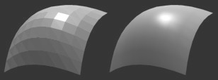
In many cases, it is difficult to perform ray-intersection calculations with true curved surfaces, especially spline patches. Therefore polygon meshes are frequently used to approximate curved surfaces. But simple displays of these meshes look blocky due to the sharp edges between individual polygons. When the polygons are triangles (as is usually the case, but the code can be adapted for quadrilaterals) a technique called "Phong shading" (invented by Bui Tuong Phong) may be used to produce the illusion of smoothness. For those familiar with the method of Gouraud shading, Phong shading is just an extension of the former. In Gouraud shading, intensities are calculated at triangle vertices and interpolated across the surface. In Phong shading, normal vectors are interpolated.
The exact procedure begins with the calculation of "smooth" or "vertex" normals. These are merely the true normals to the original curved surface. Two triangles sharing a vertex also share the smooth normal at that vertex. A good way of approximating the smooth normal at a vertex without knowing the curve equation is to just add the unit plane normals of all the triangles sharing that vertex and convert to a unit vector. We repeat this procedure for all the vertices in the mesh. Once the smooth normals at the vertices have been calculated, we can approximate the smooth normal at any point on the mesh by linear interpolation. This means that for a point P belonging to triangle T, the smooth normal at P is the weighted average of the smooth normals at the three vertices of T. The weighting factors may be calculated using scanline methods or by considering sub-triangle areas (described below). Finally, the interpolated smooth normal is used for lighting calculations. It should be stressed that Phong shading is a method for faking smoothness: the silhouette of the mesh will be inconsistent with the smooth appearance.
Note: An elegant way of calculating the weighting values for interpolation involves joining the point to the three vertices of the triangle it belongs to with straight lines. This divides the triangle into three small triangles. Now we use the area of a small triangle, divided by the total area of the triangle, as the weighting value for the smooth normal at the opposite vertex. This method is good for interpolating other quantities like colour across a triangle as well, but not textures. The procedure involves operations similar to those used to calculate the plane equation of the triangle, hence invariant values may be stored and reused.
Pixel stands for "Picture Element". It is one of the many little coloured dots that you see when you look very closely at a TV or computer screen (well, not counting vector displays, but who uses them nowadays?). Patterns such as text or images are displayed on the screen as an array of pixels set to various colours. Screen resolutions are specified as the number of pixels that the device can support. For instance, a 640x480 display has 640 columns and 480 rows of pixels, making a total of 307200 pixels in all. Similarly, there are 800x600 and 1024x768 displays. These are probably the three most commonly used resolutions, but there are many other esoteric resolutions as well.
Actually, "pixel" can mean any of the coloured dots used to describe a picture. However, since such bitmapped pictures are almost always displayed on TV or computer screens, the usage of the word has been restricted. Most printers produce pixelated images, but the term "dot" has gained wider acceptance here: we're all familiar with the acronym dpi (dots per inch) used to describe printer resolution.
A plane surface is, essentially, a flat surface. It can be thought of as the 3-D analogue of the 2-D straight line. More formally, a plane is an infinite surface such that no straight line not contained in it can intersect it more than once. The equation of a plane in Cartesian coordinates is

where a, b, c, d are constants. These have geometrical significance: the vector (a, b, c) is the normal to the plane, and |d| is the perpendicular distance of the plane from the origin. Polygons, the most widely used and fundamental primitives in 3-D modelling, are nothing but finite regions of planes. Ray-intersection calculations are very easy with planes, since they have linear (first degree) equations, hence raytracers often use bounding volumes having plane surfaces (usually cuboids). Other graphics operations such as clipping also commonly involve planes.
Sometimes, the word "plane" is used to describe the analogue of the 2-D straight line in any number of dimensions, not just 3-D. The word "hyperplane" is more common in this context. Such a plane in n dimensions is also called an (n - 1)-flat.
A point light is a light source which has no dimensions. In other words, it emits light radially in all directions from a fixed point. Point lights are especially convenient for raytracing, since only a single definite shadow ray needs to be processed for a point emitter and lighting calculations are also simplified. It may be noted here that a single point light produces very sharp, geometrical shadows. To soften the edges of the shadows, area lights and volume lights may be modelled as aggregates of point lights.
A polygon is a finite region of a plane bounded by closed sequences of straight line segments known as "edges" or "sides" (there is more than one sequence when the polygon has holes). The points of intersection of the sides are known as "vertices" (plural of "vertex"). The simplest polygon is the triangle, which has three edges and three vertices. A quadrilateral has 4 edges, a pentagon 5 and so on. The number of edges and vertices in a polygon are always equal.
Polygons are commonly used as modelling and rendering primitives. This is mainly due to fact that planes are computationally very easy to handle, and a large enough number of polygons (a mesh) can approximate just about any shape. The only slightly tricky problem with polygons is deciding whether a point is inside or outside one. This is not as easy as it sounds even for simple polygons (try doing it for a triangle without any previous knowhow!). The most general method is the odd-even edge-crossing rule. The procedure is: take a ray starting from the point and extending in a direction such that it lies in the plane of the polygon but does not pass through any of its vertices. Now count the number of intersections of the ray with the polygon edges. If the number is even, the point is outside the polygon, and if it is odd, it is inside. This algorithm is based on the principle that if the point is outside, then the entry of the ray into the polygon must be immediately followed by an exit. Thus the intersections will occur in pairs and the total will be even. A similar argument shows that if the point is inside, the number of intersections will be odd.
The expression  , where n is an integer, is called a "polynomial" in x. Usually, real values of a0, a1, ... are considered. In other words, a polynomial is a function of a variable in which the only operations are addition and multiplication and all occurrences of the variable quantity have positive integral exponents. More generally, a function of several variables satisfying similar conditions may also be called a polynomial. For example, the expression
  is a polynomial in x and y.
A primitive is a fundamental structure used in modelling. Those familiar with the programming language Java will know that the built-in types int, float etc are called primitives. These are fundamental and cannot be resolved into simpler elements. However, they can be combined to create larger, composite data structures. Graphics primitives follow the same principle: these are fundamental shapes used to describe a scene. A raytracing program almost always has the primitives sphere, polygon, cylinder etc.
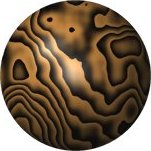
Textures can be applied to an object in two ways. Firstly, a pre-rendered image may be mapped on to the surface of the object. Secondly, a function (or "procedure") may be used to mathematically generate the surface properties at any point. The latter method is known as "procedural texturing". Almost any function can be used to generate a procedural texture, but trigonometric and noise functions are commonly used. Very convincing displays of wood, marble, stone and other materials can be created with this method. Procedural textures have very low storage requirements (just enough to store the function code) and are infinitely scalable (i.e. they can be magnified without loss of detail).