Home | Raytracing Reference | Help
A vector is a quantity that has magnitude as well as direction in space. It is usually represented as a set of offsets (or "components") in the various coordinate directions. For example, the vector V having components (3, 6, 5) represents the direction obtained by moving 3 steps in the x-direction, 6 steps in the y-direction and 5 steps in the z-direction. The magnitude of the vector V(x, y, z) is sqrt(x^2 + y^2 + z^2): it is written as |V|. The two vectors (1, 2, 3) and (2, 4, 6) have the same direction but different magnitudes. A "unit vector" is a vector whose magnitude is 1: it may be obtained by multiplying any vector V by 1/|V| as described below.
Vectors may undergo various operations such as:
Addition of two vectors A(ax, ay, az) and B(bx, by, bz):
A + B = (ax+bx, ay+by, az+bz)
Difference of two vectors A(ax, ay, az) and B(bx, by, bz):
A - B = (ax-bx, ay-by, az-bz)
Multiplication of a vector V(x, y, z) by a scalar s:
V * s = (s.x, s.y, s.z)
Dot product of two vectors A(ax, ay, az) and B(bx, by, bz) making angle W between them:
A.B = |A||B|cos W = ax.bx + ay.by + az.bz
Cross product of two vectors A(ax, ay, az) and B(bx, by, bz) making angle W between them:
A x B = (|A||B|sin W)u
where u is a unit vector perpendicular to both A and B (the direction of u is found by curving the fingers of the right hand from A to B -- the thumb will then point in the required direction). In terms of components, the cross product is calculated as
A x B = (ay.bz-az.by, az.bx-ax.bz, ax.by-ay.bx)
Vectors may also be used to represent positions of points in space. For example, the vector P(px, py, pz) represents a position reached by moving px units in the x-direction, py units in the y-direction and pz units in the z-direction from the origin. Such vectors are known as "position vectors". A position vector indicates the direction and length of the motion we must make to travel from a reference point to the point under consideration.
Vectors are of prime importance in innumerable branches of mathematics (especially geometry), physics etc. They are indispensable in computer graphics, and are intrinsic in nearly all 3-D rendering techniques. For more information, consult a high-school level mathematics or physics textbook.
Usually, the orientation of a camera is specified using three quantities: the eye position E, the position to look at L, and the up direction V. These quantities may be transformed to provide us with an orthogonal coordinate system in which the u-direction is towards the right hand side of the observer, the v-direction is upwards and the n-direction is from the eye towards the look-at point. These are known as "view coordinates" or the "uvn system". This is a left-handed system: there are also right-handed view coordinates in which the u-direction is towards the left hand side of the observer. The axis directions of the left-handed uvn system are calculated as
n = unit(L - E)
u = unit(V x N)
v = n x u
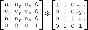
It is often desirable to transform objects from the world coordinates into the view coordinates. This makes future operations such as applying projections or clipping to view volumes much simpler. If E has components (x0, y0, z0), u has components (ux, uy, uz), v has components (vx, vy, vz) and n has components (nx, ny, nz), then the matrix for transforming objects into view coordinates is

The application of this viewing transformation is not very important for raytracers and is seldom used. However, the construction of the uvn system is important for generating primary rays from the eye.
The view plane is a plane surface positioned in front of the eye. The rendered picture is merely the projection of the scene onto the the view plane, with appropriate lighting and visibility tests.
Sometimes, we want to render only those objects which lie within certain visibility boundaries. For example, we usually do not want to render objects behind the view plane (we don't have eyes at the back of our heads!). Nor do we want to render objects that lie so far to the sides of the scene that they are not contained in the final image, or those that lie too far to the back and must, for reasons of efficiency, be eliminated. For these reasons, graphics programs sometimes define a "view volume", which is a region of space within which only those objects satisfying the above criteria lie. Before rendering, all objects are clipped to the view volume so that extraneous parts are eliminated.
Volumetric rendering is the process of displaying images of volume data, i.e. data that tells us about the appearance of an entire 3-dimensional region of space, instead of a 2-dimensional surface. An example of volumetric rendering is the raytracing of density maps. Fog, mist, flares, fire etc may be rendered with volumetric methods, as well as models of solid objects which contain information about the interior of the objects.