Home | Raytracing Reference | Help
A Bezier curve, named after Pierre Bezier, a French engineer, is an approximation spline. It has the properties that it always passes through its first and last control points, and lies in the convex hull of the control points. It is represented as the parametric function of the variable u, where u varies from 0 to 1:

where Pu is the position vector of the point on the curve with parameter u, Ck is the position vector of the kth control point and n is the total number of control points. BEZ(u, k, n) is a "Bezier basis (blending) function". It is given by the formula

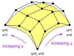
A bicubic patch is an extension of the concept of the cubic spline. It is a curved surface described with a 4x4 grid of 16 control points. Its basis functions are the products of two independent cubic spline basis functions. For example, if the cubic spline basis functions are fi(u) and gj(v), each of degree 3, where i, j vary from 0 to 3, then the parametric equation of the bicubic patch corresponding to these two splines is

where Puv is the point on the surface with parameters u, v and Cij is the position vector of the control point at position (i, j) in the grid.
See also: spline patch

A bitmap is a picture stored as an array (not necessarily rectangular) of pixel intensities, as opposed to the vector graphics format of storing object shapes as equations. A standard bitmap is rectangular and stored as an ordered sequence of intensities, in compressed (e.g. CompuServe GIF) or uncompressed (e.g. Windows BMP) form
A blobby object (or "blob") is a shape described as the boundary of a density function. This density function is usually a polynomial or exponential function that falls from a finite positive value to zero as the distance from a base point or line increases to infinity. The surface of the blobby object is the locus of the point at which the blobby function assumes, say, 50% of its maximum value. Often, a composite blobby object is created as the sum of one or more simple blobby functions. These composite objects may be used to realistically model organic shapes, liquid drop nucleus models or molecular electron orbitals. Examples of blobby objects are metaballs and Gaussian bumps.

A Boolean solid is an object that is formed by implementing the basic Boolean operations AND, OR and NOT on a set of solid primitives. E.g. if we have two solids, a sphere and a cylinder which intersect in space, then the Boolean solid "sphere AND NOT cylinder" will represent a sphere with a cylindrical hole cut out of it. Boolean operations on solids are an alternative way of expressing the functions of Constructive Solid Geometry (CSG).
In a raytracer, 90% of the rendering time may be spent in object-intersection calculations. For many objects, computing the points of intersection with a ray is a tedious and time-consuming process. However, in many cases, the ray will not intersect the object at all, but time will be wasted in determining this fact. To speed things up, bounding volumes are used. A bounding volume is merely a simple invisible geometrical shape, such as a sphere or a cuboid, which tightly encloses the object. Before testing for intersections with the object itself, we test for intersections with its bounding volume. Since bounding volumes are essentially simple shapes, this calculation is fast. If the ray intersects the bounding volume, only then do we consider intersections with the object. Otherwise, the object is ignored and little time is lost.
A BVH is a hierarchical structure of bounding volumes to speed up raytracing. Say we have an object composed of 1000 primitives. We first create a bounding volume for the entire object. Two or more new bounding volumes are generated by subdividing this volume. These are subdivided in turn, and so on, with the child volumes becoming smaller and smaller and containing fewer and fewer primitives. When each of the child volumes contains no more than, say, 20 primitives, we stop the process. The resulting structure is a tree of bounding volumes, from largest to smallest. This is known as a "Bounding Volume Hierarchy (BVH)". When we calculate intersections of a ray with the object, we first test it against the root volume. If it hits this, we test it against its child volumes. Say it hits the first child volume but not the others. We now test the ray against the children of the first child volume. This process is repeated until we have narrowed the search down to only a few small bounding volumes. Thus the task of considering intersections with 1000 primitives is reduced to the much quicker task of considering intersections with only 20 or 30.
See also: space subdivision
A box is a cuboid, or a rectangular parallopiped (why do I get the feeling that I'm thinking up tongue-twisters for something that is self-explanatory?). It is a polyhedron with 6 rectangular surfaces (with opposite ones of equal area), 12 edges and 8 vertices. All the angles between adjacent faces and edges are right angles (90 degrees). When all edges are of equal length, a box is termed a "cube".
A B-spline is an approximation spline like the Bezier curve. It possesses the advantages of local control (which means that you can change one part without affecting the others) and degree independent of the number of control points. The B-spline basis functions are given by the Cox-De Boor recursive formula, specified in relation to an ordered set of numbers known as a "knot vector".
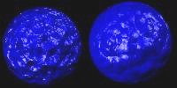
Bump mapping is a technique of adding fake surface detail such as graininess and bumpiness by warping the surface normal procedurally before applying the lighting calculations. For example, to create the illusion of dents in a golf ball, a function that warps the the normal as if the surface was covered with small circular concavities is used. However, bump mapping is suitable only for small details: since it does not actually modify the shape of the surface, the silhoutte will be inconsistent with the bumps.
