Home | Raytracing Reference | Help
In 3-D graphics, a camera is a structure that contains data about the viewer position, that is, where the viewer is located in the scene, which way he/she is looking, which direction is up, which direction is the right and so on. It is used to define the view coordinates of a scene. The transformation from world coordinates to view coordinates is often a preliminary to the rendering process. The name "camera" is due to the fact that in the real world, the positioning of a camera is a pre-requisite to taking a photograph.
Often, the display of a scene or picture must be restricted to a particular volume or area. The process by which parts of the scene outside this boundary are eliminated is called clipping. Clipping is more important in real time renderers than in raytracing. The most common clipping operation is clipping to the view plane, so that only objects in front of this are preserved (this is necessary, because you shouldn't be able to see what's behind your back). In raytracers, this particular operation is automatically implemented by the specification that the distance along the ray to the intersection point must be positive (where a positive distance is measured in the direction of the ray, a negative one in the opposite direction). Other clipping operations include clipping to view volumes, clipping to screen, window or polygon boundaries, and clipping to portals.
It is difficult to define colour, although it has an instinctive meaning to all of us. It is a property of a substance by which we may distinguish it from other substances of different colours just by looking at it. Fundamentally, colour is the property, or index of the property, of a substance to reflect, produce or transmit light of specific wavelengths more than others. Something which predominantly reflects light of low wavelengths (the red end of the spectrum) is said to have red colour. Something else which reflects light of high wavelengths is violet, and so on. The graph of the predominance of certain wavelengths in light is an index of colour.
Colour is frequently represented in computer graphics applications as having three components -- usually Red, Green, and Blue (RGB). These components (primaries) have certain standard wavelengths. By combining suitable amounts of these components, any colour can be exactly or approximately represented. A better set of components is the set of three CIE primaries, but these are not as intuitive to us as RGB, nor do they have physical equivalents. The Cyan, Magenta, Yellow (CMY) scheme is frequently used in hard copy output devices. This is complementary to the RGB scheme: R+G = Y, G+B = C, R+B = M. Other schemes include the Hue, Luminance, Saturation (HLS) scheme and the XYZ scheme.
Strictly speaking, a cone is the locus of a straight line that passes through a fixed point (vertex) and a fixed curve in 3-D space. In most cases, this curve is assumed to be an ellipse and the word "cone" is used to refer to this particular case. The strictly-defined cone is a double cone, that is, it has two halves, meeting at the vertex, which are exactly similar but oppositely oriented. However, we often further restrict the word "cone" to describe the shape of one of these halves. Such a cone describes the shape of an ice-cream cornet, or a witch's hat. A cone is a quadric: when the vertex is at the origin, it has the equation
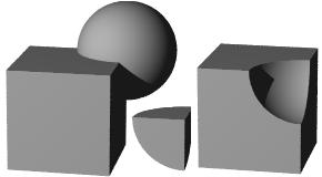
CSG is a method of building up complex solids by applying simple grouping operations to a set of primitive solids. The common CSG operations are union, intersection and difference. An union is merely a group of solids. An intersection consists of the part that is common to all the solids. A difference is the part of a solid that remains after subtracting (cutting away) another solid from it. In raytracing, CSG is implemented with inside-outside tests. For instance, if a CSG intersection of two objects A and B was to be rendered, then only the parts of A inside B and the parts of B inside A would be displayed. In the usual algorithm, as soon as an intersection point on A is found, it is tested to see if it is inside B. If it is not, then it is discarded. The same applies to B, with the roles of A and B reversed.
A coordinate system is a way of uniquely addresing each point in space or in a data set for the purposes of spatial measurement and location. As a simple example, the latitudes and longitudes on the surface of Earth form a coordinate system. A coordinate system in n-dimensional space has n variable parameters.
The most commonly used coordinate system is the set of Cartesian coordinates. In 2-D space, this is composed of the x and y axes, straight lines at right angles to each other. Any point in this space can be uniquely expressed in terms of two parameters: the x and y coordinates, which define how far we need to move up or down the x and y axes respectively to get to the point. In 3 dimensions, we add an extra axis, the z-axis, which is at right angles to both x and y axes. Along with x and y coordinates, we now have to specify the z-coordinate, i.e. how far down the z-axis the point lies. This system is extensible to any number of dimensions. n-Dimensional space has n coordinates: {x1, x2, x3, ..., xn}.

Computer graphics applications typically use a Cartesian coordinate system. Raster monitors implement a simple Cartesian pixel reference scheme: the screen, say at 640x480 resolution, is composed of 640 columns and 480 rows of pixels. Each pixel is addressed with two independent parameters: row and column. Thus the pixel with coordinates (10, 5) is on the 5th column of the 10th row. Be careful, many authors and applications use the reverse system of (column, row).
Predictably enough, the Cartesian system isn't the only one around. There are hundreds of other coordinate systems, many having nothing to do with physical space and used only to reference points in a system with multiple independent parameters. One example is the space-time system where, in addition to the usual 3 coordinates of space, we have the extra coordinate of time. On a par with the Cartesian system are polar and cylindrical coordinates, derived from the techniques of addressing points on the surfaces of a sphere and a cylinder respectively. These are especially useful in texture-mapping, where data from the Cartesian system of a bitmap must be mapped to a spherical, cylindrical or similar surface.
A coordinate system allows us to calculate the spatial relationships between points. For example, the distance between two points (x1, y1, z1) and (x2, y2, z2) is
sqrt[(x1 - x2)^2 + (y1 - y2)^2 + (z1 - z2)^2]
Shapes can be expressed with equations. We know that a sphere is the set of points at a fixed distance, the radius, from a fixed point, the centre. Knowing the distance formula, and assuming the centre is at (Cx, Cy, Cz) and the radius is R, we can describe the sphere as the set of all points (x, y, z) satisfying the equation
sqrt[(x - Cx)^2 + (y - Cy)^2 + (z - Cz)^2] = R, or
(x - Cx)^2 + (y - Cy)^2 + (z - Cz)^2 = R^2
A cubic is a polynomial of degree 3. Often, cubic refers to a shape described as a polynomial function of the coordinates (say x, y, z), such that the highest degree of any term is 3. A cubic equation is an equation of the form f(x) = 0, where f(x) is a cubic polynomial. The method of solving this equation is due to two Italian mathematicians, Niccolo Tartaglia and Gerolamo Cardano. There is some speculation that Tartaglia was the original discoverer and Cardano merely refined the solution (Tartaglia actually accused Cardano of stealing his method).
See also: cubic spline
A cubic spline is a spline which is expressed as a cubic polynomial function of a parameter u. A point Pu on this curve is given by

where a, b, c, d are vectors. Normally, a cubic spline is described in relation to a number (usually 4) of control points.
A cylinder is the locus of a straight line which passes through a fixed curve and is parallel to a fixed straight line (the "axis") in 3-D space. Usually, the fixed curve is assumed to be an ellipse and the word "cylinder" is used to refer to this particular case. When the curve is a circle, the resulting shape is called a circular cylinder. A circular cylinder is the locus of a point which is equidistant from the axis. A roll of toilet paper is a good example of a circular cylinder: the axis runs right through the centre of the hole in the middle, coinciding with the rod of the dispensing spool. A cylinder is a quadric: if the axis is the z-axis, then the equation of the (elliptic) cylinder is

Note that this is nothing but the equation of an ellipse in 2 dimensions.